書籍「組み込みエンジニアの教科書」URL
SECTION-15●LEDをON/OFFする実験
組込みの勘所を掴むという目的から、筆者はGUIを一切使わずコマンド上でのビルドおよび書き込みを行う事例を紹介しています。 詳細は書籍を購入してご確認ください。


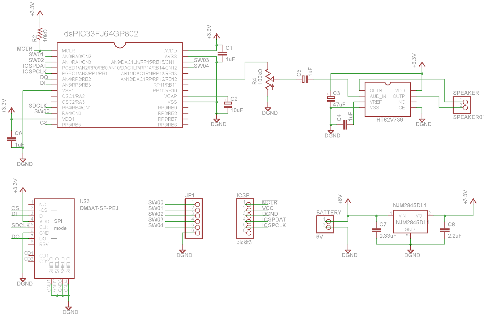
基板で動いた。電源のノイズは若干ある pic.twitter.com/8qLFZPDGdi
— とりまあ@マルチコプター製作中 (@Trimming_ly) 2015, 8月 27


/*****************************************************************************

                Microchip Memory Disk Drive File System

 *****************************************************************************
 * FileName:        main_15_08_11_01.c
 * Dependencies:    FSIO.h
 * Processor:       dsPIC33E, PIC24E
 * dsPIC33F64GP802
 * Compiler:        C30
 * Company:         Microchip Technology, Inc.
 *
 * Note:  This file is included to give you a basic demonstration of how the
 *           functions in this library work.  Prototypes for these functions,
 *           along with more information about them, can be found in FSIO.h
 *****************************************************************************/

//DOM-IGNORE-BEGIN
/********************************************************************
 Change History:
  Rev            Description
  ----           -----------------------
  1.3.4          Initial Revision
********************************************************************/
//DOM-IGNORE-END

/*******************************************************************************
//NOTE : DISABLE MACRO "SUPPORT_LFN" IN "FSconfig.h" FILE TO WORK WITH THIS DEMO
         EFFECTIVELY. DISABLING "SUPPORT_LFN" WILL SAVE LOT OF MEMORY FOR THIS
         DEMO.
********************************************************************************/

/******************************************************************************
 * プログラム内容
 *
 * MDDFSによるmicroSDの読み書きプログラムに44.1kHzのDAC割込みが入るプログラムを
 * 付け足したプログラム。
 * このプログラムを実行すると44.1kHzのDAC割込みが常に入り、割込み関数内でRA0ピンを
 * 反転させている。
 ******************************************************************************/

/***********************************************************************
 *         プログラム全体にかかわる、初期設定
 ***********************************************************************/

/********************************
 *   ヘッダー と 定数
 ********************************/
#define FCY 39628800UL
#define PI 3.14159265359
#define SIN(x)  sin(PI/180*x)

#include <xc.h>
#include <math.h>
#include <libpic30.h>
//#include "./p33FJ64GP802.h"
#include "./FSIO.h"

/********************************
 *   コンフィギュレーション
 ********************************/
#pragma config BWRP = WRPROTECT_OFF
#pragma config BSS = NO_BOOT_CODE
#pragma config RBS = NO_BOOT_RAM
#pragma config SSS = NO_SEC_CODE
#pragma config GWRP = OFF
#pragma config GSS = OFF
#pragma config FNOSC = FRCPLL
#pragma config IESO = OFF
#pragma config POSCMD = NONE
#pragma config OSCIOFNC = ON
#pragma config FCKSM = CSECMD
#pragma config FWDTEN = OFF
#pragma config FPWRT = PWR16
#pragma config ALTI2C = ON
#pragma config ICS = PGD1
#pragma config JTAGEN = OFF

/********************************
 *    グローバル変数
 ********************************/
const char sendBuffer[] = "Hello MDDFS";
char send2[] = "2";
char receiveBuffer[50];

/********************************
 * ユーザー定義関数 プロトタイプ
 ********************************/
void init_clock(void);      // クロックの初期設定
void init_pps(void);        // ペリフェラルピンセレクトのピン設定
void init_gpio(void);       // 入出力ピンの設定
void init_dac(void);         // AudioDACの初期設定


/***********************************************************************
 *               関 数 群
 ***********************************************************************/

/********************************
 *     メイン関数
 ********************************/
int main (void)
{
    FSFILE * pointer;

    // Activate the RTCC module
    __builtin_write_RTCWEN();
    Nop();
    Nop();
    RCFGCALbits.RTCPTR0 = 1;
    RCFGCALbits.RTCPTR1 = 1;

    // Set it to the correct time
    // These values won't be accurate
    RTCVAL = 0x0011;
    RTCVAL = 0x0815;
    RTCVAL = 0x0108;
    RTCVAL = 0x2137;
    RCFGCAL = 0x8000;

    init_clock();
    init_pps();
    init_gpio();
    init_dac();

    while(1);

    while (!MDD_MediaDetect());
    // Initialize the library
    while (!FSInit());

/*
   // Open file 1 in read mode
    pointer = FSfopen ("FILE1.TXT", "r");
    if (pointer == NULL){
        //ERROR();
        while(1);
    }

   // Read one "r_byte"-byte object
    r_byte = 5; // 1バイト読み取り
    if(FSfread (receiveBuffer, r_byte, 1, pointer) != 1){
        //ERROR();
        while(1);
    }

   // Check if this is the end of the file- it shouldn't be
    if (FSfeof (pointer)){
        //ERROR();
        while(1);
    }
    // Close the file
    if (FSfclose (pointer)){
        //ERROR();
        while(1);
    }
    __delay_ms(1000);
    if(receiveBuffer[0] == 'a') LATAbits.LATA0 = 1;
    __delay_ms(1000);
    if(receiveBuffer[1] == 'b') LATAbits.LATA1 = 1;
    __delay_ms(1000);
    if(receiveBuffer[2] == 'c') LATAbits.LATA2 = 1;
    __delay_ms(1000);
    if(receiveBuffer[3] == 'd') LATAbits.LATA3 = 1;
    __delay_ms(1000);
    if(receiveBuffer[4] == 'e') LATAbits.LATA4 = 1;
*/

    // Create a file
    pointer = FSfopen ("FILE2.TXT", "w");
    if (pointer == NULL){
      while(1);
    }

    // Write 21 1-byte objects from sendBuffer into the file
    if (FSfwrite (sendBuffer, 1, sizeof(sendBuffer), pointer) != sizeof(sendBuffer)){
        while(1);
    }

    // FSftell returns the file's current position
    if (FSftell (pointer) != sizeof(sendBuffer)){
        while(1);
    }

    // FSfseek sets the position one byte before the end
    // It can also set the position of a file forward from the
    // beginning or forward from the current position
    if (FSfseek(pointer, 1, SEEK_END)){
      while(1);
    }

    // Close the file
    if (FSfclose (pointer)){
        while(1);
    }
    while(1);
}

/********************************
 * ペリフェラルピンセレクトの設定
 *  主にSPIピンの設定
 ********************************/
void init_pps()
{
    /*
     * ----Initialize Peripheral Pin Select of SPI----
     *      <入力の割り当て>
     * [入力名]                      [機能名]   [レジスタ]   [コンフィグレーションビット]
     * SPI1データ入力                 SDI1      RPINR20      SD1R
     * SPI1クロック入力               SCK1      RPINR20      SCK1R
     *
     *      <出力の割り当て>
     * [出力名]                      [機能名]    [RPnR]
     * RPnをSPI1データ出力に接続      SDO1        00111
     * RPnをSPI1クロック出力に接続    SCK1OUT     01000
     *
     * CS(Chip Select)  は   RB5
     */
    TRISBbits.TRISB5 = 0;       // CSは出力端子

    /**************************************************
     *            Un lock Registers                   *
     **************************************************/
    __builtin_write_OSCCONL(OSCCON & 0xDF);

    /**************************************************
     *            Configure Input functions           *
     **************************************************/
    // Assign "SDI1" To Pin "RP2"   (RB2)
    RPINR20bits.SDI1R = 2;

    // Assign "SCK1" To Pin "RP3"  dsPICがマスターだから使わないかも。
    //RPINR20bits.SCK1R = 3;a

    /**************************************************
     *            Configure Output functions          *
     **************************************************/
    // Assign "SDO1" To Pin "RP3"
    RPOR1bits.RP3R = 0b00111;
    // Assign "SCK1OUT" To Pin "RP4"
    RPOR2bits.RP4R = 0b01000;

    /**************************************************
     *                Lock Registers                  *
     **************************************************/
    __builtin_write_OSCCONL(OSCCON | 0x40);
}

/********************************
 *    汎用入出力の設定
 ********************************/
void init_gpio()
{
    AD1PCFGL = 0xFFFF;
    TRISA = 0x00;
    TRISBbits.TRISB2 = 1;       // RB2(SDI1) is in pin
    TRISBbits.TRISB3 = 0;       // RB3(SDO1) is out pin
    TRISBbits.TRISB4 = 0;       // RB4(CKOUT)is out pin

    LATA = 0x0000;              // PORTAを全て0で初期化
    LATB = 0x0000;
}

/********************************
 *    動作クロックの設定
 ********************************/
void init_clock()
{
    // Initialize and configure Primary PLL, and enable Secondary Oscillator
    // Fvco = 7.3728MHz / N1 * M = 158.515MHz
    // Fosc = Fvco / N2 = 158.515MHz / 2 = 79.258MHz
    // Fcy = Fosc / 2 = 39.629MHz
    PLLFBDbits.PLLDIV = 41;     // M = 43
    CLKDIVbits.PLLPOST = 0;     // N2 = 2
    CLKDIVbits.PLLPRE = 0;      // N1 = 2

    CLKDIVbits.ROI = 0;         // Interrupts have no effect on the DOZEN bit
    CLKDIVbits.DOZE = 0;        // Fcy / 1
    CLKDIVbits.DOZEN = 0;       // disable DOZE
    CLKDIVbits.FRCDIV = 0;      // FRC/1(default)

    ACLKCONbits.AOSCMD = 0b00;  // 補助オシレータ(Aosc)を無効にする(規定値だけど)
                                // 必然的に補助クロックはPLL出力を参照
    ACLKCONbits.APSTSCLR = 0b111;
}

/********************************
 *   Audio DACの設定
 ********************************/
void init_dac()
{
    DAC1STATbits.ROEN = 1;      // Right Channel DAC Output Enabled
    DAC1STATbits.LOEN = 1;      // Left Channel DAC Output Enabled

    DAC1STATbits.RITYPE = 0;    // Right Channel Interrupt if FIFO is empty
    DAC1STATbits.LITYPE = 0;    // Left  Channel Interrupt if FIFO is empty

//    DAC1STATbits.LMVOEN = 0;    // Midpoint DAC output is anabled
//    DAC1STATbits.RMVOEN = 0;    // Midpoint DAC output is anabled

    DAC1CONbits.AMPON = 0;      // Amplifier Disabled During Sleep and Idle Modes
    // Fs = 44.1kHz
    // Fs(kHz) * 256 = 11.2896MHz
    // Fvco(MHz) / 11.2896MHz = 14.041 ≒ 14
    DAC1CONbits.DACFDIV = 13;   // Divide Clock by 14
    DAC1CONbits.FORM = 0;       // Data Format is Unsigned

    DAC1DFLT = 0x8000;          // Default Value set to Midpoint when FORM

    IFS4bits.DAC1RIF = 0;       // Clear Right Channel Interrupt Flag
    IFS4bits.DAC1LIF = 0;       // Clear Left  Channel Interrupt Flag

    IEC4bits.DAC1RIE = 1;       // Right Channel Interrupt Enabled
    IEC4bits.DAC1LIE = 1;       // Left  Channel Interrupt Enabled

    DAC1CONbits.DACEN = 1;      // DAC1 Module Enabled
}

/********************************
 *   Audio DAC 割込み関数
 ********************************/
//-- ライトチャネル
void __attribute__((interrupt, no_auto_psv))_DAC1RInterrupt(void)
{
    LATAbits.LATA0 =  ~LATAbits.LATA0;
    IFS4bits.DAC1RIF = 0;       // Clear Right Channel Interrupt Flag
    DAC1RDAT = 0x8000;          // User Code to Write to FIFO Goes Here
}

//-- レフトチャネル
void __attribute__((interrupt, no_auto_psv))_DAC1LInterrupt(void)
{
    IFS4bits.DAC1LIF = 0;       // Clear Right Channel Interrupt Flag
    DAC1LDAT = 0x8000;          // User Code to Write to FIFO Goes Here
}
/*
/*
 * File:   main_15.08.02.01.c
 * Author: kota
 *
 * Created on 2015/07/17, 17:15
 */


/***********************************************************************
 *         プログラム全体にかかわる、初期設定
 ***********************************************************************/

/********************************
 *   ヘッダーのインクルード
 ********************************/
#define FCY 24413125UL

#include <libpic30.h>
#include <xc.h>
/********************************
 *   コンフィギュレーション
 ********************************/
#pragma config BWRP = WRPROTECT_OFF
#pragma config BSS = NO_BOOT_CODE
#pragma config RBS = NO_BOOT_RAM
#pragma config SSS = NO_SEC_CODE
#pragma config GWRP = OFF
#pragma config GSS = OFF
#pragma config FNOSC = FRCPLL
#pragma config IESO = OFF
#pragma config POSCMD = NONE
#pragma config OSCIOFNC = ON
#pragma config FCKSM = CSECMD
#pragma config FWDTEN = OFF
#pragma config FPWRT = PWR16
#pragma config ALTI2C = ON
#pragma config ICS = PGD1
#pragma config JTAGEN = OFF

/********************************
 * ユーザー定義関数 プロトタイプ
 ********************************/
void init_gpio(void);
void init_clock(void);
void init_dac(void);


/***********************************************************************
 *               関 数 群
 ***********************************************************************/

/********************************
 *     メイン関数
 ********************************/
int main(void) {
    init_clock();
    init_gpio();
    //init_dac();

    while(1){
        LATAbits.LATA0 = 1;
        __delay_ms(1);
        LATAbits.LATA0 = 0;
        __delay_ms(1);
    }
    return 0;
}

/********************************
 *    動作クロックの設定
 ********************************/
void init_clock()
{
    CLKDIVbits.ROI = 0;         // Interrupts have no effect on the DOZEN bit
    CLKDIVbits.DOZE = 0;        // Fcy / 1
    CLKDIVbits.DOZEN = 0;       // disable DOZE
    CLKDIVbits.FRCDIV = 0;      // FRC/1(default)
    // Initialize and configure Primary PLL, and enable Secondary Oscillator
    PLLFBDbits.PLLDIV = 51;     // M = 53
    CLKDIVbits.PLLPOST = 1;     // N2 = 4
    CLKDIVbits.PLLPRE = 0;      // N1 = 2
    // Fvco = 7.3728MHz / N1 * M = 195.3792MHz
    // Fosc = Fvco / N2 = 48.845MHz
    // Fcy = Fosc / 2 = 24.422MHz

    ACLKCONbits.SELACLK = 0;    // PLL出力(Fvco参照)
    //ACLKCONbits.ASRCSEL = 1;    // DAC用クロックは主クロックを使用
    ACLKCONbits.APSTSCLR = 0b111;
}

/********************************
 *      GPIOの設定
 ********************************/
void init_gpio()
{
    AD1PCFGL = 0xFFFF;          // アナログ入出力をオフに
    TRISA = 0x0000;             // RA0-
    LATA = 0x0000;              // 出力を0に初期化
}

/********************************
 *   Audio DACの設定
 ********************************/
void init_dac()
{
    DAC1STATbits.ROEN = 1;      // Right Channel DAC Output Enabled
    DAC1STATbits.LOEN = 1;      // Left Channel DAC Output Enabled

    DAC1STATbits.RITYPE = 0;    // Right Channel Interrupt if FIFO is empty
    DAC1STATbits.LITYPE = 0;    // Left  Channel Interrupt if FIFO is empty

//    DAC1STATbits.LMVOEN = 0;    // Midpoint DAC output is anabled
//    DAC1STATbits.RMVOEN = 0;    // Midpoint DAC output is anabled

    DAC1CONbits.AMPON = 0;      // Amplifier Disabled During Sleep and Idle Modes
    // Fs = 44.1kHz
    // Fs(kHz) * 256 = 11.2896MHz
    // Fvco(MHz) / 11.2896MHz =  17.31 ≒ 17
    DAC1CONbits.DACFDIV = 16;    // Divide Clock by 17
    DAC1CONbits.FORM = 0;       // Data Format is Unsigned

    DAC1DFLT = 0x8000;          // Default Value set to Midpoint when FORM

    IFS4bits.DAC1RIF = 0;       // Clear Right Channel Interrupt Flag
    IFS4bits.DAC1LIF = 0;       // Clear Left  Channel Interrupt Flag

    IEC4bits.DAC1RIE = 1;       // Right Channel Interrupt Enabled
    IEC4bits.DAC1LIE = 1;       // Left  Channel Interrupt Enabled

    DAC1CONbits.DACEN = 1;      // DAC1 Module Enabled
}

/********************************
 *   Audio DAC 割込み関数
 ********************************/
//-- ライトチャネル
void __attribute__((interrupt, no_auto_psv))_DAC1RInterrupt(void)
{
    IFS4bits.DAC1RIF = 0;       // Clear Right Channel Interrupt Flag
    LATAbits.LATA0 = ~LATAbits.LATA0;
    DAC1RDAT = 0x0000;          // User Code to Write to FIFO Goes Here
}

//-- レフトチャネル
void __attribute__((interrupt, no_auto_psv))_DAC1LInterrupt(void)
{
    IFS4bits.DAC1LIF = 0;       // Clear Right Channel Interrupt Flag
    DAC1LDAT = 0x8000;          // User Code to Write to FIFO Goes Here
}


/*
 * File:   main_15.08.02.01.c
 * Author: Chatteringok
 *
 * Created on 2015/07/17, 17:15
 */


/***********************************************************************
 *         プログラム全体にかかわる、初期設定
 ***********************************************************************/

/********************************
 *   ヘッダーのインクルード
 ********************************/
#define FCY 24413125UL

#include <libpic30.h>
#include <xc.h>
/********************************
 *   コンフィギュレーション
 ********************************/
#pragma config BWRP = WRPROTECT_OFF
#pragma config BSS = NO_BOOT_CODE
#pragma config RBS = NO_BOOT_RAM
#pragma config SSS = NO_SEC_CODE
#pragma config GWRP = OFF
#pragma config GSS = OFF
#pragma config FNOSC = FRCPLL
#pragma config IESO = OFF
#pragma config POSCMD = NONE
#pragma config OSCIOFNC = ON
#pragma config FCKSM = CSECMD
#pragma config FWDTEN = OFF
#pragma config FPWRT = PWR16
#pragma config ALTI2C = ON
#pragma config ICS = PGD1
#pragma config JTAGEN = OFF

/********************************
 * ユーザー定義関数 プロトタイプ
 ********************************/
void init_gpio(void);
void init_clock(void);
void init_dac(void);


/***********************************************************************
 *               関 数 群
 ***********************************************************************/

/********************************
 *     メイン関数
 ********************************/
int main(void) {
    init_clock();
    init_gpio();
    init_dac();

    while(1){
    }
    return 0;
}

/********************************
 *    動作クロックの設定
 ********************************/
void init_clock()
{
    CLKDIVbits.ROI = 0;         // Interrupts have no effect on the DOZEN bit
    CLKDIVbits.DOZE = 0;        // Fcy / 1
    CLKDIVbits.DOZEN = 0;       // disable DOZE
    CLKDIVbits.FRCDIV = 0;      // FRC/1(default)
    // Initialize and configure Primary PLL, and enable Secondary Oscillator
    PLLFBDbits.PLLDIV = 51;     // M = 53
    CLKDIVbits.PLLPOST = 1;     // N2 = 4
    CLKDIVbits.PLLPRE = 0;      // N1 = 2
    // Fvco = 7.3728MHz / N1 * M = 195.3792MHz
    // Fosc = Fvco / N2 = 48.845MHz
    // Fcy = Fosc / 2 = 24.422MHz

    ACLKCONbits.SELACLK = 0;    // PLL出力(Fvco参照)
    ACLKCONbits.APSTSCLR = 0b111;
}

/********************************
 *      GPIOの設定
 ********************************/
void init_gpio()
{
    AD1PCFGL = 0xFFFF;          // アナログ入出力をオフに
    TRISA = 0x0000;             // RA0-
    LATA = 0x0000;              // 出力を0に初期化
}

/********************************
 *   Audio DACの設定
 ********************************/
void init_dac()
{
    DAC1STATbits.ROEN = 1;      // Right Channel DAC Output Enabled
    DAC1STATbits.LOEN = 1;      // Left Channel DAC Output Enabled

    DAC1STATbits.RITYPE = 0;    // Right Channel Interrupt if FIFO is empty
    DAC1STATbits.LITYPE = 0;    // Left  Channel Interrupt if FIFO is empty

//    DAC1STATbits.LMVOEN = 0;    // Midpoint DAC output is anabled
//    DAC1STATbits.RMVOEN = 0;    // Midpoint DAC output is anabled

    DAC1CONbits.AMPON = 0;      // Amplifier Disabled During Sleep and Idle Modes
    // Fs = 44.1kHz
    // Fs(kHz) * 256 = 11.2896MHz
    // Fvco(MHz) / 11.2896MHz =  17.31 ≒ 17
    DAC1CONbits.DACFDIV = 16;    // Divide Clock by 17
    DAC1CONbits.FORM = 0;       // Data Format is Unsigned

    DAC1DFLT = 0x8000;          // Default Value set to Midpoint when FORM

    IFS4bits.DAC1RIF = 0;       // Clear Right Channel Interrupt Flag
    IFS4bits.DAC1LIF = 0;       // Clear Left  Channel Interrupt Flag

    IEC4bits.DAC1RIE = 1;       // Right Channel Interrupt Enabled
    IEC4bits.DAC1LIE = 1;       // Left  Channel Interrupt Enabled

    DAC1CONbits.DACEN = 1;      // DAC1 Module Enabled
}

/********************************
 *   Audio DAC 割込み関数
 ********************************/
//-- ライトチャネル
void __attribute__((interrupt, no_auto_psv))_DAC1RInterrupt(void)
{
    IFS4bits.DAC1RIF = 0;       // Clear Right Channel Interrupt Flag
    LATAbits.LATA0 = ~LATAbits.LATA0;
    DAC1RDAT = 0x0000;          // User Code to Write to FIFO Goes Here
}

//-- レフトチャネル
void __attribute__((interrupt, no_auto_psv))_DAC1LInterrupt(void)
{
    IFS4bits.DAC1LIF = 0;       // Clear Right Channel Interrupt Flag
    DAC1LDAT = 0x8000;          // User Code to Write to FIFO Goes Here
}
